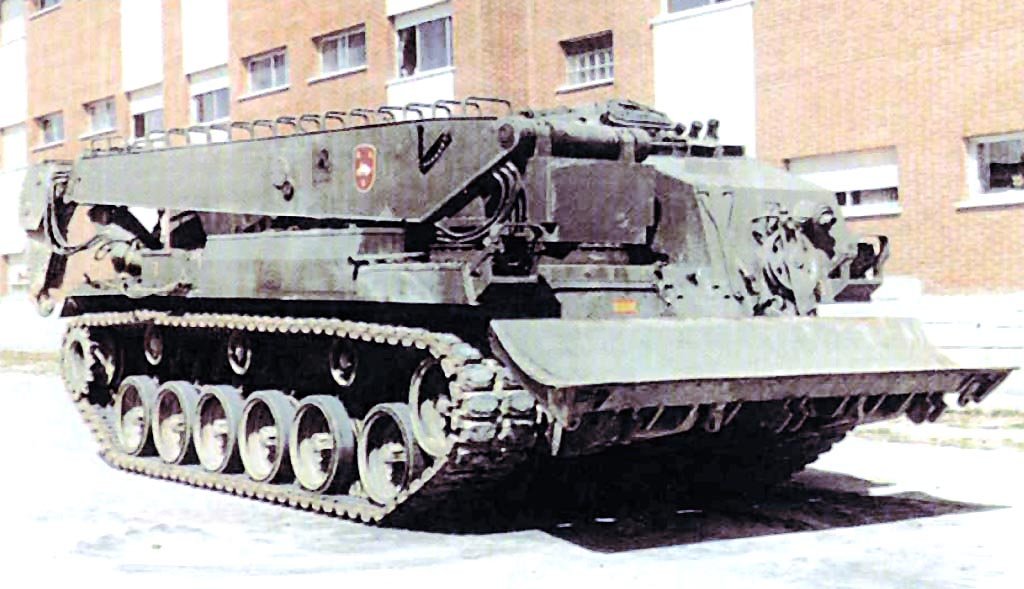
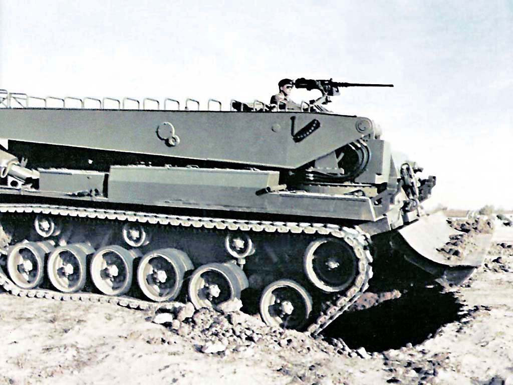
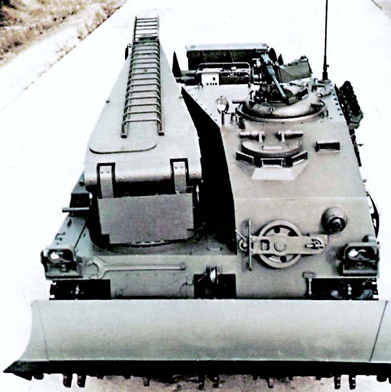
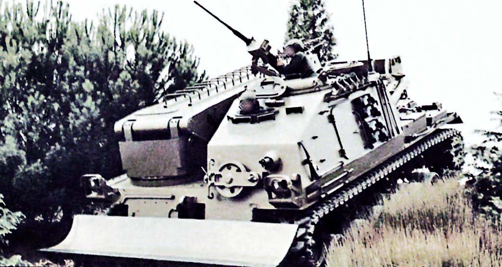
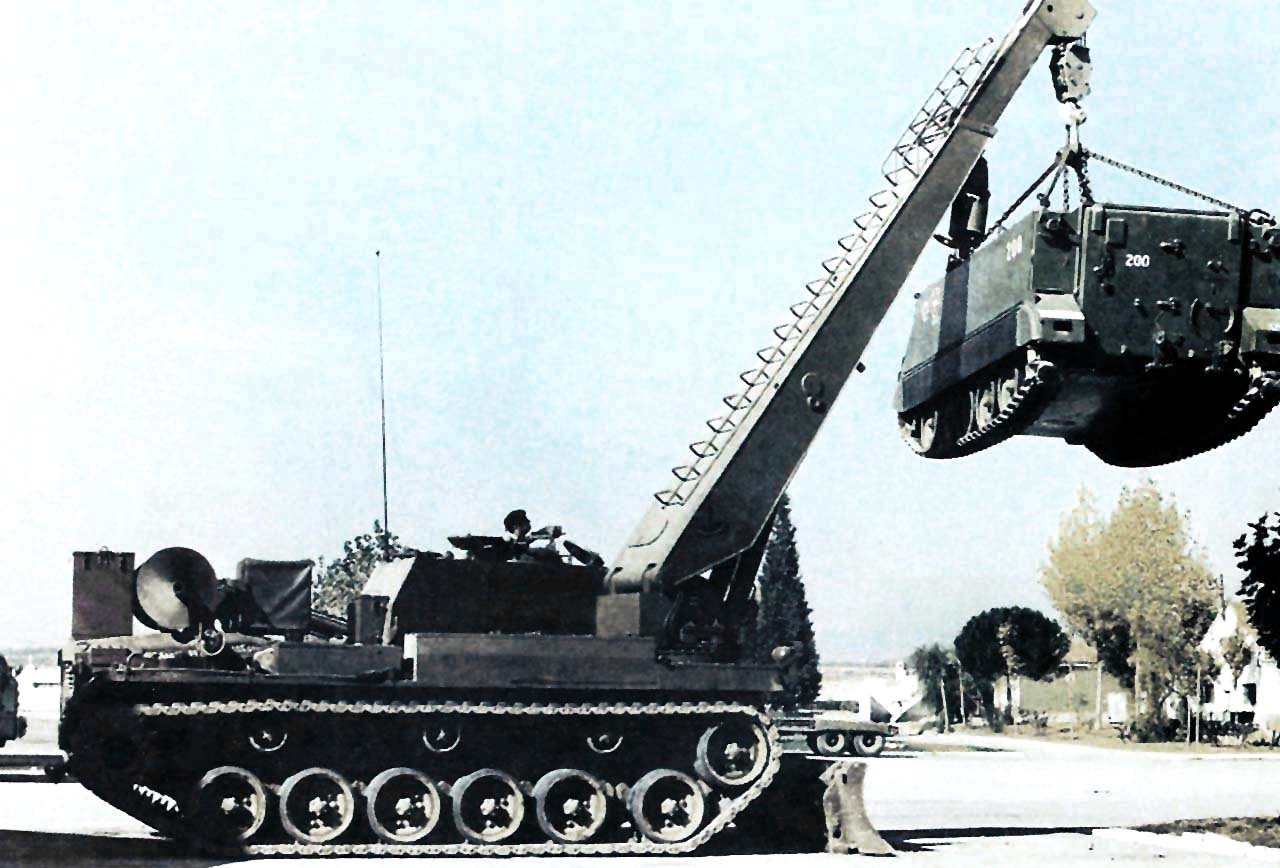
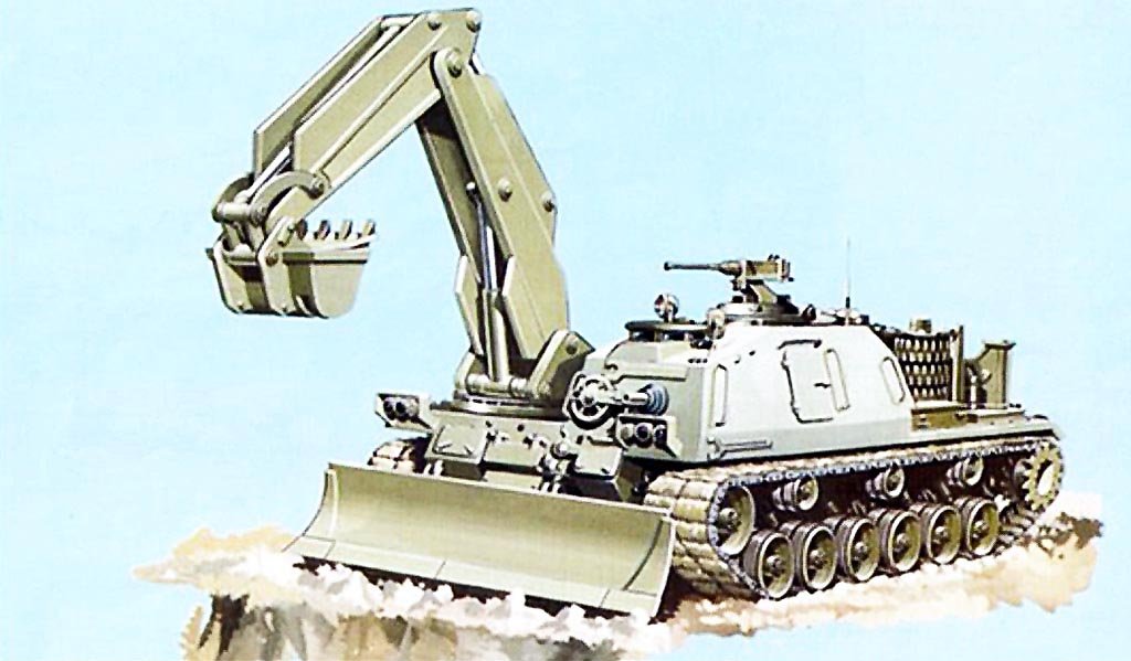
In the 1980s, the Spanish Army lacked a dedicated armored/combat engineer vehicle, so the Spanish firm Talbot S.A. offered three specific vehicles to address this need. A project was presented for a bridge-laying vehicle, designated the M-47E2 LP, but not even a prototype was ever built. Talbot also produced an armoured recovery vehicle (ARV) prototype, designated the M-47E2R, and a combat engineer vehicle (CEV) prototype, designated the M-47E2I. All three vehicles were developed using the hull of the American M-47E medium tank, which was in service with the Spanish Army and was clearly outdated, although its chassis was perfectly suitable for conversion into specialized engineering vehicles.The new M-47E2I engineer vehicle was introduced in September 1981 and was externally identical to the M-47E2R recovery vehicle. Of course, the engineer vehicle had some specific equipment, although it shared some systems with the recovery vehicle. The chassis was the same, so its running gear consisted of six double road wheels on each side and three double support rollers, with the idler wheel at the front and the drive wheel at the rear. Logically, the suspension was also the same and consisted of torsion bars with hydraulic shock absorbers on the first, second, fifth, and sixth road wheels. The armament was also the same, consisting of a 12.7mm M-2 machine gun mounted on the right side of the commander’s cupola with 600 rounds and a 7.62mm MG-1A3S machine gun mounted on a ball mount at the front of the vehicle with 2,000 rounds. The M-47E2I CEV also carried six smoke grenade dischargers positioned similarly to the M-47E2R, and had a smoke-generating exhaust system (TEESS) capability for concealment.The M-47E2I used the same 760 hp Continental AVDS-1790-2D diesel engine as the M-47E2R, coupled to the same Allison CD 850-6A transmission, achieving a top speed of 56 km/h on roads and a range of approximately 600 km. It could overcome vertical obstacles of 0.91 meters, climb gradients of up to 60%, cross trenches 2.60 meters wide, and ford watercourses 1.20 meters deep without preparation. The armor consisted of welded steel plates and offered complete protection against small arms fire and splinters.In the M-47E2I AEV prototype, the turret was removed and an armored superstructure was built to house the three crew members and the controls for operation, direction and work. This superstructure occupied the front left half of the hull and consisted of a trapezoidal superstructure with a door on the left side.The crew consisted of three members: commander, driver, and an machine gunner/operator. The driver sat in the front right position with the front machine gunner/operator to his left. Behind the driver, in a higher position, was the commander, which had a small observation cupola. The driver had three M-17 sight blocks and an AN/VVS-2 passive sight with a light intensifier, as did the commander, whose sights were mounted on the cupola. Finally, the forward-firing machine gunner also had an M-17 sight.This vehicle incorporated a 6.55-meter-long crane with an extendable jib. With the jib extended, the crane measured 8.55 meters and served as a tower for aerial work. The crane had a 360° rotation range, and a ladder topped with a small platform was installed on the boom. The M-47E2I used the same dozer blade and winch as the M-47E2R. The blade was 3.65 meters wide and 0.88 meters high, with a pulling force of 35 tons and a performance of 200 cubic meters per hour. The TR-650 winch was a cassette type and had a maximum pulling force of 35 tons, reaching up to 70 tons using a double pull and a shunt pulley. This system was located in the center of the hull and had two electronically controlled operating speeds. It had a 33mm diameter, 100-meter long steel cable that exited through the front of the hull via a hydraulic tensioner and a release valve. These three systems were hydraulically operated and driven by two pumps powered by the main engine.M-47E2I’s specific engineering equipment consisted of a hydraulic drill for ground boring. This system comprised an extension and a drill bit and had a total length of 3.40 meters. The extension was installed using a special fitting on the crane arm, and then the drill bit was inserted. The drill bit was 1.90 meters long and had a diameter of 0.75 meters, allowing a drilling depth of 3 meters. The drill was carried on a support mounted transversely at the rear of the hull above the engine. Other specific engineering equipment carried on board consisted of an 8 hp self-contained generator, a compressor, an electric shock starter, four power take-offs (two electric, one hydraulic and one mechanical), a tool kit, and detonators and blasting equipment arranged in several armored boxes.Once completed, Talbot S.A. delivered the M-47E2I CEV prototype to the 12th Engineer Battalion of the 12th Armored Brigade “Guadarrama” in October 1981, although some sources place this date in 1984. In any case, the vehicle underwent successful trials with this unit at least until 1986, when the Army’s Engineer Inspectorate was created, which redefined the concept of a new engineer vehicle. In 1988 a new concept was presented, and in this new vehicle, the crane and drill were replaced by a backhoe with a 180° turning angle, a reach of 6.50 meters, and a throughput of 45 cubic meters per hour. This new vehicle was designated the M-47E2Z (on the image), but it ultimately remained in the design phase, and no prototype was ever built.